
Bringing up Windows 10 AArch64 on a $50 Single Board Computer

imbushuo
Please mind the gap
Disclaimer: From a customer's perspective, you might not be interested in this article.
Abstract
Windows on ARM is not a new topic. There are some guys attempted to bring up Windows RT and Windows 10 on Qemu (ARM/AArch64 target). It even runs on Raspberry Pi 3. Obviously it is not a Snapdragon 835-only thing. We can give it a hand on our own Single Board Computers.
This article covers some important details in Dragonboard 410c SBC's aa64 UEFI implementation.
Wait...Why this article is written in English?
Because my Chinese Input Method is broken (it frequently hangs Visual Studio Code). Realizing there's no need for me to use Chinese IME frequently, I decided to uninstall it for a more pleasant experience.
Contents
- Windows Boot Requirements
- Bootstrapping your own EDK2/TianoCore UEFI
- Memory Allocation / Memory Management Unit
- UEFI Flash Definition
- First-stage Bootloader (Little Kernel)
- Persistent NVRAM Support
- A "Working" RTC
- Multi-processor startup (PSCI)
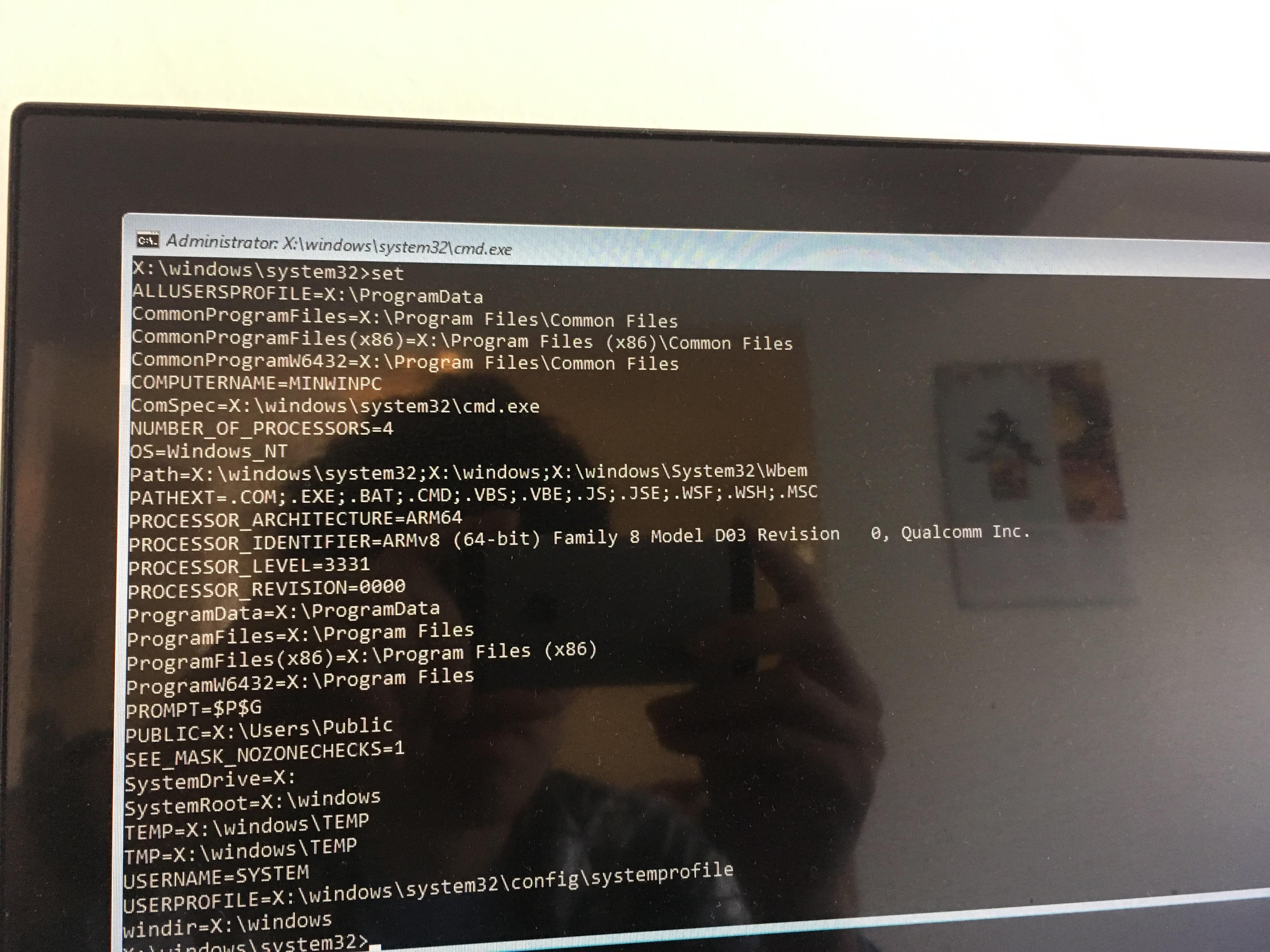
Windows Boot Requirements (AArch64):
- AArch64 architecture processor. It seems that AArch64 cryptography extension is required too (Raspberry Pi 3 randomly throws UNSUPPORTED_PROCESSOR bugcheck. The BCM2837 SoC doesn't implement this extension). According to known source, this requirement is probably removed in RS4.
- For multi-processor systems, either Microsoft ARM Multi-processor Parking Protocol or ARM PSCI interface shall be implemented. All current Windows 10 IoT ARM32 platforms implement former one.
- A working interrupt controller. Most AArch64 SoC cores include ARM GIC, so there's little work to do here. The only exception I know is BCM2837. Windows actually has inbox Broadcom interrupt controller support (for the sake of Raspberry Pi). But if your SoC has additional third party interrupt controller, you need to supply your own HAL extension library. There is few documentation for this available though...
- A working processor timer. If not, supply your own HAL extension library.
- Complete ACPI 5.1/6.0 and UEFI 2.3+ implementation. Do not try to use Das U-Boot's EFI implementation; it's broken.
These requirements are fairly similar to ARM SBBR certification requirements. If your SBC has a working EDK2/TianoCore UEFI, then you are probably good to go. Bootstrapping your own EDK2 is pretty easy too.
Bootstrapping your own EDK2/TianoCore
The board I used (DragonBoard 410c) doesn't have a known EDK2/TianoCore implementation. So I have to build my own. This repository for Raspberry Pi 3 is a good start point and reference for you.
You need to do these things in UEFI:
- Initialize serial output (for debugging) and Memory Management Unit (MMU). Refer to your platform datasheet for device memory address allocation.
- Retrieve required information from pre-UEFI environment and build Hand-off Blocks (HOB) for DXE phase
- Initialize processor (exception vector, etc.) in DXE phase.
- Initialize required peripherals (GPIO, GIC, eMMC, USB, RTC, Display...) in DXE phase.
- Initialize UEFI services (variable services) in DXE phase.
- Jump to BDS phase, start Windows Boot Manager or something else.
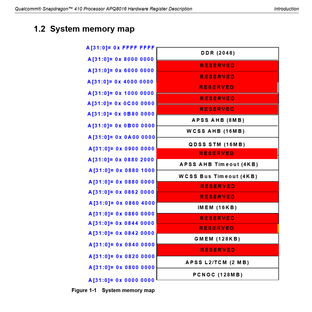
Memory Allocation / Memory Management Unit
Memory allocation is a platform-specific thing. Check your platform HRD to get some idea about MMU and memory allocation. For Snapdragon 410, check out Qualcomm LM80-P0436-13.
UEFI Flash Definition
Our UEFI FD starts at 0x80200000. Update your tokens in platform definition and flash definition:
[FD.Apq8016\_EFI]
BaseAddress   = 0x80200000|gArmTokenSpaceGuid.PcdFdBaseAddress  #The base address of the FLASH Device.
Size          = 0x00120000|gArmTokenSpaceGuid.PcdFdSize         #The size in bytes of the FLASH Device
ErasePolarity = 1
BlockSize     = 0x200
NumBlocks     = 0x900

# 512 bytes of configuration header & 8 bytes of image header
0x00000000|0x00120000
gArmTokenSpaceGuid.PcdFvBaseAddress|gArmTokenSpaceGuid.PcdFvSize
FV = FVMAIN\_COMPACT
And the first piece code should be your SEC initialization code (without relocation).
[FV.FVMAIN\_COMPACT]
FvAlignment        = 8
ERASE\_POLARITY     = 1
MEMORY\_MAPPED      = TRUE
STICKY\_WRITE       = TRUE
LOCK\_CAP           = TRUE
LOCK\_STATUS        = TRUE
WRITE\_DISABLED\_CAP = TRUE
WRITE\_ENABLED\_CAP  = TRUE
WRITE\_STATUS       = TRUE
WRITE\_LOCK\_CAP     = TRUE
WRITE\_LOCK\_STATUS  = TRUE
READ\_DISABLED\_CAP  = TRUE
READ\_ENABLED\_CAP   = TRUE
READ\_STATUS        = TRUE
READ\_LOCK\_CAP      = TRUE
READ\_LOCK\_STATUS   = TRUE

  INF DragonboardPkg/Sec/Sec.inf
Little Kernel (mentioned below) will be responsible for jumping into UEFI FD at 0x80200000 and handing off execution. If you want, you can actually removes Android-specific header and device tree validation in LK (apps/aboot.c).
First-stage bootloader (Little Kernel)
DragonBoard 410c uses ARM Secure Monitor Call to switch to AArch64 mode (See Qualcomm LM80-P0436-1 for more information). The stock close-sourced SBL does not recognize AArch64 ELF files (later model should). LK performs basic platform initialization (UART, eMMC, MMU, etc.) A modified variant LK also initializes FrameBuffer for U-Boot. We can make it work for our UEFI too.
Windows requires UEFI provide a BGRA FrameBuffer. To achieve this, we need to modify pixel unpack pattern in platform/msm_shared/mdp5.c:
case 32:
    /* Windows requires a BGRA FB */
    writel(0x000236FF, pipe\_base + PIPE\_SSPP\_SRC\_FORMAT);
    writel(0x03020001, pipe\_base + PIPE\_SSPP\_SRC\_UNPACK\_PATTERN);
You can either specify a hard-coded address for FrameBuffer, or have a random piece of memory block to transfer information (pixel format, width, height, etc.) to UEFI. UEFI SEC phase retrieve the information, allocate HOB block and transfer information to DXE phase. A simple FrameBuffer driver retrieve information from HOB block, initializes UEFI Graphics Output Protocol. For optimal performance, initialize this piece of memory block as write-through cache memory in MMU initialization.
Persistent NVRAM Support
For persistent NVRAM support, it's a good idea to use eMMC as storage device. This implementation demonstrates how to simulate NVRAM using eMMC and a piece of memory. I slightly modified it make it work for Qualcomm devices:
- If eMMC NVRAM region is corrupted or uninitialized, provision it and perform a platform warm reset so I don't get a synchronous exception in volatile variable initialization phase.
- Modify dependency relationship to prevent "device not found" error in BlockRamVariable DXE initialization.
A "working" RTC
Windows Boot Manager depends on a "working" Real Time Clock for miscellaneous purposes. APQ8016/MSM8916 has a RTC on its PMIC processor PM8916. To access RTC services, read/write SPMI registers (see Qualcomm LM80-P0436-36). If you are lazy, just use Xen fake RTC in ArmVirtPkg.
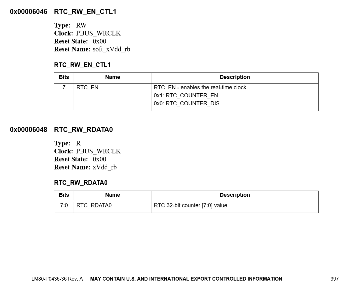
RTC HRD in LM80-P0436-36To enable PM8916 RTC, set SPMI register 0x6046 to enabled state, then read 0x6048 and three following bits:
EFI\_STATUS Status = EFI\_SUCCESS;
UINTN secs = 0;
UINT32 readNum = 0;
UINT8 value[NUM\_8\_BIT\_RTC\_REGS];

for (UINTN i = 0; i < 4; i++)
{
  Status = Pm8916Protocol->ReadPmic(
    Pm8916Protocol,
    PM8916\_RTC\_READ\_ADDR + i,
    &value[i],
    1,
    &readNum
  );

  if (EFI\_ERROR(Status))
  {
    DEBUG((EFI\_D\_ERROR, "Failed to read PMIC RTC epoch bit %d\n", i));
    return EFI\_DEVICE\_ERROR;
  }

  readNum = 0;
}

if (value[0] < 0)
{
  DEBUG((EFI\_D\_ERROR, "PM8916 RTC reported error.\n"));
  return EFI\_DEVICE\_ERROR;
}

// Convert RTC epoch time
secs = value[0] | (value[1] << 8) | (value[2] << 16) | (value[3] << 24);
// Remember our offset
secs = secs + mRtcOffset;

// Convert UNIX epoch to EFI time.
EpochToEfiTime(secs, Time);
Note: I implemented my own PMIC protocol called *PM8916Protocol *that read/writes PMIC register on SPMI bus, slave #0. This RTC library is based on Xen face RTC library from ArmVirtPkg.
4KB / 64KB Page Table
For most single board computers, you will probably hit issues in ExitBootServices. EDK2 assumes runtime world follows 64KB/Page memory allocation, while most single board computers supply only less than 2GB memory. On these boards, MMU will run in 4KB PT mode. To resolve the issue, go to MdePkg/Include/AArch64/ProcessorBind.h:
///
/// The stack alignment required for AARCH64
///
#define CPU\_STACK\_ALIGNMENT  16

///
/// Page allocation granularity for AARCH64
///
#define DEFAULT\_PAGE\_ALLOCATION\_GRANULARITY   (0x1000)

///
/// For the sake of our SBCs
///
#define RUNTIME\_PAGE\_ALLOCATION\_GRANULARITY   (0x1000)
Set runtime page allocation granularity to 0x1000 (4KB). If your board has memory larger than 2GB, you should not modify this value; instead, check your memory allocation. There's another interesting case with 4KB/64KB page on Cortex A53.
ARM Erratum
I randomly hit crashes (synchronous exception) during my UEFI development. After some investigation, it seems that the problem is related to load/store commands. (See ARM Errata 835769, 843419) To prevent random crashes, add these two flags to your GCC compiler:
-mfix-cortex-a53-835769 -mfix-cortex-a53-843419
If you don't correctly handle ARM SIMD instruction traps, set these switches too:
-mstrict-align -mgeneral-regs-only
Multi-Processor Startup (PSCI)
For platforms that implement ARM PSCI, indicate PSCI support in ACPI FADT table:
EFI\_ACPI\_6\_0\_HW\_REDUCED\_ACPI | EFI\_ACPI\_6\_0\_LOW\_POWER\_S0\_IDLE\_CAPABLE,    // UINT32     Flags
{
  EFI\_ACPI\_6\_0\_EMBEDDED\_CONTROLLER,
  0,
  0,
  EFI\_ACPI\_6\_0\_DWORD,
  0x009020B4
},                                                                        // EFI\_ACPI\_6\_0\_GENERIC\_ADDRESS\_STRUCTURE  ResetReg
1,                                                                        // UINT8      ResetValue
EFI\_ACPI\_6\_0\_ARM\_PSCI\_COMPLIANT,                                          // UINT16     ArmBootArchFlags
EFI\_ACPI\_6\_0\_FIXED\_ACPI\_DESCRIPTION\_TABLE\_MINOR\_REVISION,                 // UINT8      MinorRevision
Typically you don't need HVC call for PSCI. If you did so (and your platform doesn't support HVC call for PSCI), you will get a INTERNAL_POWER_ERROR bugcheck with first parameter of 0x0000BEEF.
If you indicates PSCI support, you don't have to provide parking protocol version in your ACPI MADT table. Simply set it to 0. Here's one example:
[02Ch 0044   1]                Subtable Type : 0B [Generic Interrupt Controller]
[02Dh 0045   1]                       Length : 50
[02Eh 0046   2]                     Reserved : 0000
[030h 0048   4]         CPU Interface Number : 00000000
[034h 0052   4]                Processor UID : 00000000
[038h 0056   4]        Flags (decoded below) : 00000001
                           Processor Enabled : 1
          Performance Interrupt Trigger Mode : 0
          Virtual GIC Interrupt Trigger Mode : 0
[03Ch 0060   4]     Parking Protocol Version : 00000000
[040h 0064   4]        Performance Interrupt : 00000017
[044h 0068   8]               Parked Address : 0000000080301000
[04Ch 0076   8]                 Base Address : 0000000000000000
[054h 0084   8]     Virtual GIC Base Address : 0000000000000000
[05Ch 0092   8]  Hypervisor GIC Base Address : 0000000000000000
[064h 0100   4]        Virtual GIC Interrupt : 00000000
[068h 0104   8]   Redistributor Base Address : 0000000000000000
[070h 0112   8]                    ARM MPIDR : 0000000000000000
[078h 0120   1]             Efficiency Class : 00
[079h 0121   3]                     Reserved : 000000
See ARM Juno reference platform to get some idea about crafting ACPI tables.
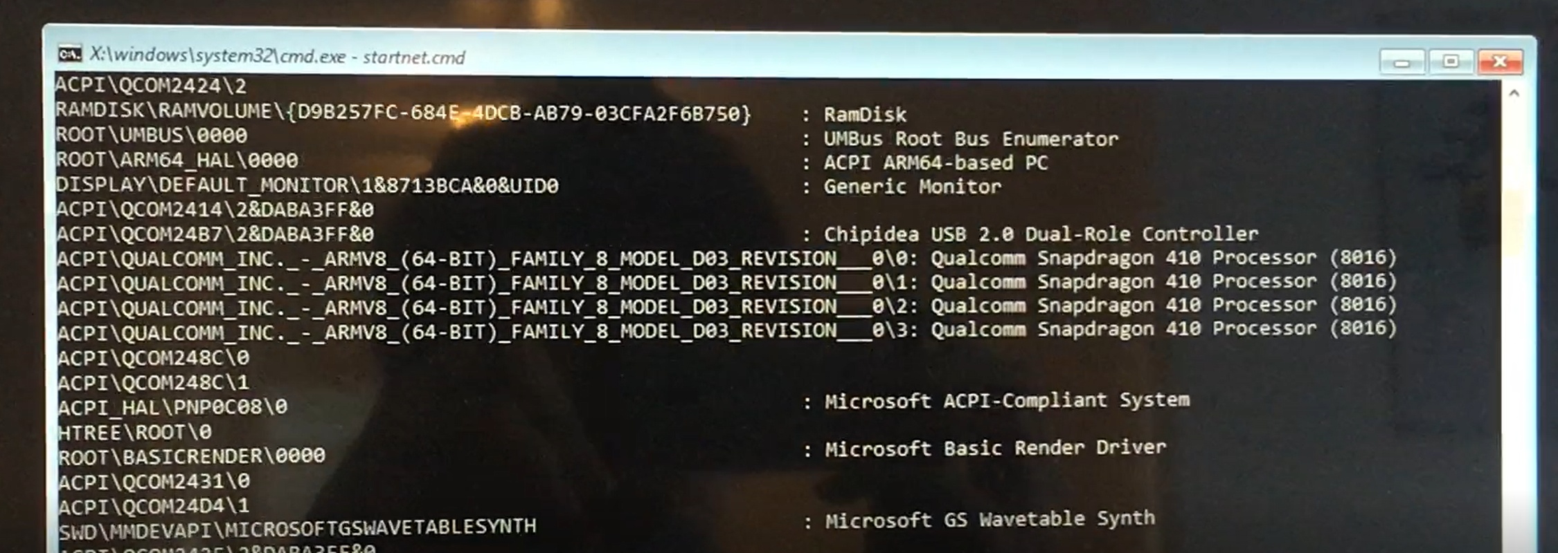
That's it! Welcome to Windows 10 Userland.
Spend some nights writing Windows drivers. :P